Deck Load Design & Calculations - Part 2
If we had determined that our soil can only have a maximum load of 750 psf we would have needed 2,700 ÷ 750 = 4 deck support columns equally spaced.
However, the positioning of the deck support columns is also critical to our deck design. To verify that each individual deck support column will not carry more than 1,250 psf we can verify our previous calculation by adding the deck support columns to our plan, as shown in Figure 3, and then calculating the load that will be subjected to each of the deck support columns of each individual load area.
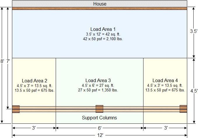
Figure 3 - Proposed deck diagram with deck support columns
In Figure 3 we have placed the deck support columns under the beam, one at each end and one in the center of the beam.
The load that each deck support column and the ledger are carrying is shown in different colors as the individual load areas. Note, that the load for area 2 and 4 are the same. The loads for areas 1 and 3 are different.
Looking at Figure 3 we can instantly see that each deck support column is not carrying an equal load. The outside deck support columns are carrying 4.5 x 3 ft = 13.5 sq. ft. at 50 psf = 675 pounds. This is only half of the load of the center deck support column which is carrying 4.5 x 6 feet = 27 sq. ft. at 50 psf = 1,350 pounds.
Based on our original design criteria of a maximum of 1,250 pounds of load per deck support column, this design is not structural sound or suitable.

Includes CAD software, deck plans and designs.
Where did we go wrong?
Although the deck support columns would appear to be equally spaced they are not, as far as what individual load each of the deck support columns are taking. If the number of deck support columns is correct, based on our original calculation, which it is, the only error can be in the positioning of the deck support columns.
To correct the load problem that has been created we must move the end deck support columns so that they are taking more of the load. Figure 4 moves the deck support columns in so that they are 1 foot from each end of the beam.
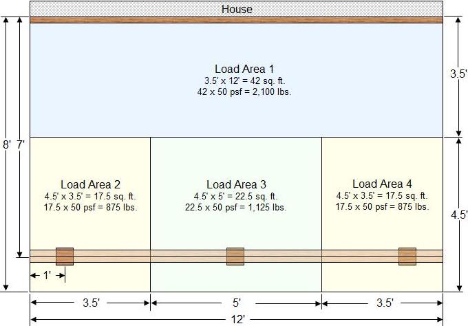
Figure 4 - Proposed deck diagram with deck support columns re-positioned
By moving the deck support columns in 1 foot, we have changed the dynamics of what load each of the deck support columns are carrying. The load for areas 2 and 4 are now carrying a load of 875 pounds each, while the center column is now carrying a load of 1,125 pounds. By making this desing change all 3 load areas that are being supported by the deck columns are below our individual deck support column design load of 1,250 pounds.
Note: It would appear that if we moved the end deck support columns in even farther than 1 foot that we would be able to balance the deck loads even more. In theory that would be correct. However, the use of cantilevers can create a host of different problems.
It is important to remember that the deck transfers its load to the ledger and the deck support columns, hence the ledge has to be properly and securely connected to the house and the columns in turn, have to transfer their load to properly designed footings.
Continue to deck support column sizing........